In a conventional compaction process, material is formed or densified mainly by mechanical pressure. For some laboratory and R&D applications, however, researchers also want to understand what happens when high-frequency vibration is introduced during pressing.
This is where ultrasonic vibro-compaction becomes interesting.
Instead of using ultrasound for welding or cutting, a 20 kHz ultrasonic system can be mechanically coupled to the press ram. The ultrasonic vibration is then superimposed on the pressing force, allowing researchers to study its effect on material movement, packing behavior and densification.
How Is Ultrasonic Vibration Added to a Compaction Press?
The basic arrangement is relatively straightforward:
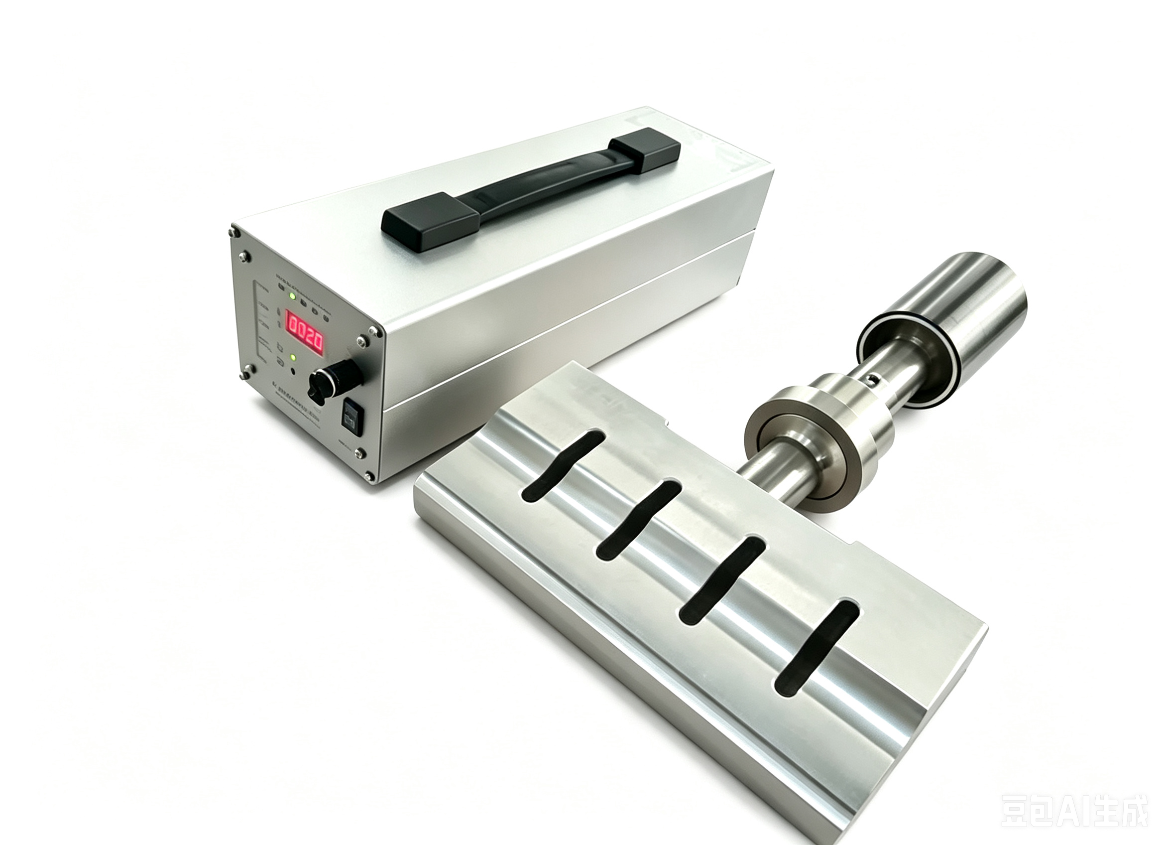
Ultrasonic Generator → Transducer → Booster → Sonotrode → Press Ram
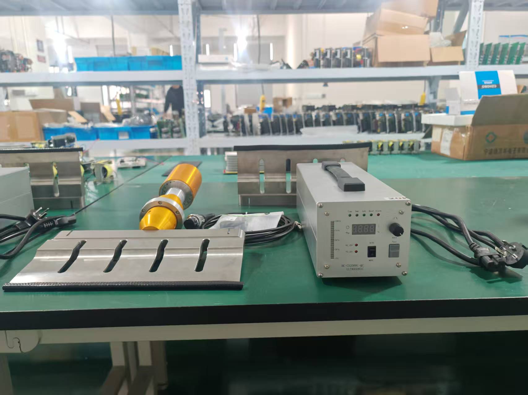
The generator drives a Langevin-type piezoelectric transducer at its resonant frequency. Mechanical vibration from the transducer passes through the booster and sonotrode before entering the press structure.
The press still provides the main compaction force. The ultrasonic system adds high-frequency mechanical excitation during the process.
For laboratory equipment, 20 kHz is a practical frequency for this type of high-power ultrasonic system. Depending on the press structure, the system can use one ultrasonic stack or several stacks installed at different positions.
Why Use More Than One Ultrasonic Transducer?
A single ultrasonic transducer introduces vibration from one location. This may be sufficient for a small tool, but vibration distribution becomes more important as the ram or working area becomes larger.
One approach is to install several ultrasonic stacks across the press ram.
For example, a three-point arrangement can use three independent 20 kHz transducer assemblies connected to the same ram. Each assembly consists of a transducer, booster and sonotrode and is powered by its own ultrasonic generator.
This gives the equipment designer more flexibility in how ultrasonic energy is introduced into the mechanical structure.
However, simply adding more transducers does not guarantee better performance. Their positions, sonotrode geometry, ram stiffness and mechanical boundary conditions all affect the actual vibration behavior.
The Sonotrode Is More Important Than It Looks
In a welding machine, the ultrasonic horn normally transfers vibration directly to the welding area. In a vibro-compaction press, its role is somewhat different.
Here, the sonotrode becomes part of the mechanical connection between the ultrasonic stack and the press ram.
This means that a standard horn cannot simply be selected from a catalogue and installed on every press.
Its dimensions and mounting interface need to be considered together with the press structure. Available installation space, operating frequency, required amplitude and mechanical loading during pressing can all influence the final design.
For this reason, we normally ask for the sonotrode or press ram drawing before manufacturing the ultrasonic tooling.
Generator Control Under Changing Loads
The mechanical load on an ultrasonic system does not always remain constant during a pressing cycle.
A digital ultrasonic generator with automatic frequency tracking can follow changes in the resonant condition of the ultrasonic stack and maintain stable operation. Power output can also be adjusted according to the requirements of the experiment.
For a multi-transducer system, each ultrasonic stack can be connected to an independent generator. This makes individual control possible and also simplifies integration with laboratory or pilot-scale equipment.
Protection against overcurrent, overheating and abnormal loads is particularly useful in experimental equipment, where operating conditions may change frequently during testing.
The Material Still Determines the Final Ultrasonic Design
There is no single ultrasonic configuration that is suitable for every compaction process.
Powder, granules and other materials can respond differently to mechanical vibration. The press structure itself also changes the vibration characteristics of the complete system.
Before selecting the ultrasonic power, amplitude and sonotrode design, two pieces of information are particularly useful:
The material or product being compacted — this helps us understand the actual process and operating conditions.
The press ram and sonotrode drawings — these allow the ultrasonic stack and mechanical interface to be evaluated properly.
For experimental systems, information such as pressing force, available installation space and the purpose of the test can further help determine the appropriate configuration.
Building an Ultrasonic Vibro-Compaction System
A typical laboratory system may include:
* 20 kHz digital ultrasonic generator
* Langevin-type piezoelectric transducer
* Booster
* Customized sonotrode
* High-frequency cables
* Air cooling
* External control interface
For applications requiring vibration at several positions, multiple ultrasonic units can be installed on the same press.
KONESONIC can supply the individual ultrasonic components or develop the ultrasonic section as an integrated system according to the press structure and experimental requirements.
Developing a Similar Application?
Ultrasonic vibro-compaction is not a standard off-the-shelf application. The ultrasonic system needs to work together with the mechanical structure of the press.
If you are developing a laboratory compaction press or another machine that requires controlled ultrasonic vibration, send us the material information and your press or sonotrode drawings.
Our engineers can evaluate the application and recommend a suitable transducer, generator and sonotrode configuration for your equipment.